
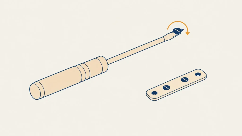
Intraoperative breakage in orthopedic surgery involves drill bits, wires and driver tips as well as screws, and for a cranial fixation driver neither ASTM F382 nor the FDA plate criteria set a durability cycle count. A defensible count follows from the reprocessing claim, a robot turns the test into a measurement, and press-fit wear needs engagement and release tracked separately.
Failure analysis in orthopedic and neurosurgical hardware has a consistent and slightly counterintuitive shape. The implant is not the only thing that breaks. The tool that installs it breaks too.
A 2020 retrospective study of 8,132 elective orthopedic cases recorded 30 instrument breakages, a rate of 0.36 percent, with drill bits the single most common item and screwdriver tips accounting for two of the thirty. A 2002 study across 7,775 procedures found 14 broken instruments in 12 cases. A 2021 series of 12,601 patients attributes 44.4 percent of breakages to K-wires, 38.9 percent to screws and 16.6 percent to drill bits. Broader operating room data is less flattering still: surgeons in a 2022 cardiac surgery study reported an equipment issue in 92 percent of operations, a 2019 study found device-related interruptions in 30 percent of laparoscopic procedures, and a 2013 systematic review attributed a median 23.5 percent of all operating room errors to equipment and technology, with a median of 0.9 equipment problems per procedure.
None of that is a warranty question. A screwdriver tip that rounds out during skull reconstruction is an intraoperative event with a patient on the table.
The program described here was a cranial fixation system using a press-fit screw-to-blade interface with a custom mechanical detachment mechanism. We develop medical device hardware at OVA Solutions, where 62 engineers have shipped more than 200 devices. On this program our scope covered mechanical design, prototyping, testing, product optimization, and the robotic validation setup. Validation ran 100 standardized insertions under constant torque to characterize mechanical durability and bit wear.
Nobody will tell you how many cycles to run
The most useful thing to know before planning this kind of validation is that the number is not published anywhere.
ASTM F382 estimates bone plate fatigue strength at a cycle count the tester specifies, and the FDA performance criteria for fracture fixation plates contain no fatigue test and leave cranial and maxillofacial plates outside their scope. ISO 7151:2024 covers general requirements and test methods for non-cutting, articulated surgical instruments. The ASTM E08.05 subcommittee covers cyclic deformation and fatigue, and F04.15 covers material test methods for medical devices.
None of it tells you how many times a driver must engage a screw head before the engagement geometry is no longer trustworthy.
The defensible way to derive that number runs through reprocessing rather than through fatigue standards. ISO 17664-1 has the manufacturer state the limits on processing a reusable device, such as a maximum number of processing cycles or another indication of the end of its life, and ISO 10993-1 expects biological evaluation to cover that same device life. The regulatory logic is that the device must remain safe and effective through its stated lifecycle. So the reprocessing claim sets the durability test count, and the two numbers should be decided together rather than by separate teams at separate times.
A validation running 100 insertions is defensible when the labeling claims 100 reprocessing cycles. It is arbitrary when the labeling claims something else, and that mismatch is an avoidable finding.
The robot is a measuring instrument
Robotic validation on a program like this gets described as automation, which undersells what it is doing. The robot is there to remove a variable, not to save labor.
Published insertion torque data shows how far torque varies on one well-defined task. An in vitro study of pedicle screw insertion reported a mean insertion torque of 2.3 Nm, standard deviation 0.9, across 100 pedicle screws in 50 vertebrae. With variation of that size from screw to screw, a wear test cannot leave torque to chance: it has to be set and recorded for every cycle.
If the experimental question is how the engagement geometry degrades with use, torque has to be held constant across every cycle. A human operator cannot do that, and a torque-limiting handle controls only the upper bound rather than the full profile of approach angle, engagement speed, and axial preload. A robotic arm holds all of it, which converts a durability test into a repeatable measurement with an isolated variable.
The practical guidance is to specify the robotic cell as part of the test method in the design history file, with the applied torque, approach vector, insertion rate, and axial load recorded per cycle. A wear result without those parameters is an anecdote.
Press-fit has a two-sided specification
A press-fit screw-to-blade interface has to do two opposite things reliably. It has to hold the screw securely enough that it does not drop or spin during placement, and it has to release cleanly when the surgeon withdraws the driver.
Wear moves both, and it moves them toward different failures. An interface that has worn loose fails at engagement, where the screw rotates in the driver and cannot be tightened. An interface that has galled or deformed fails at release, where the screw stays on the driver after placement, which is the more disruptive of the two because it happens after the surgeon believes the step is complete.
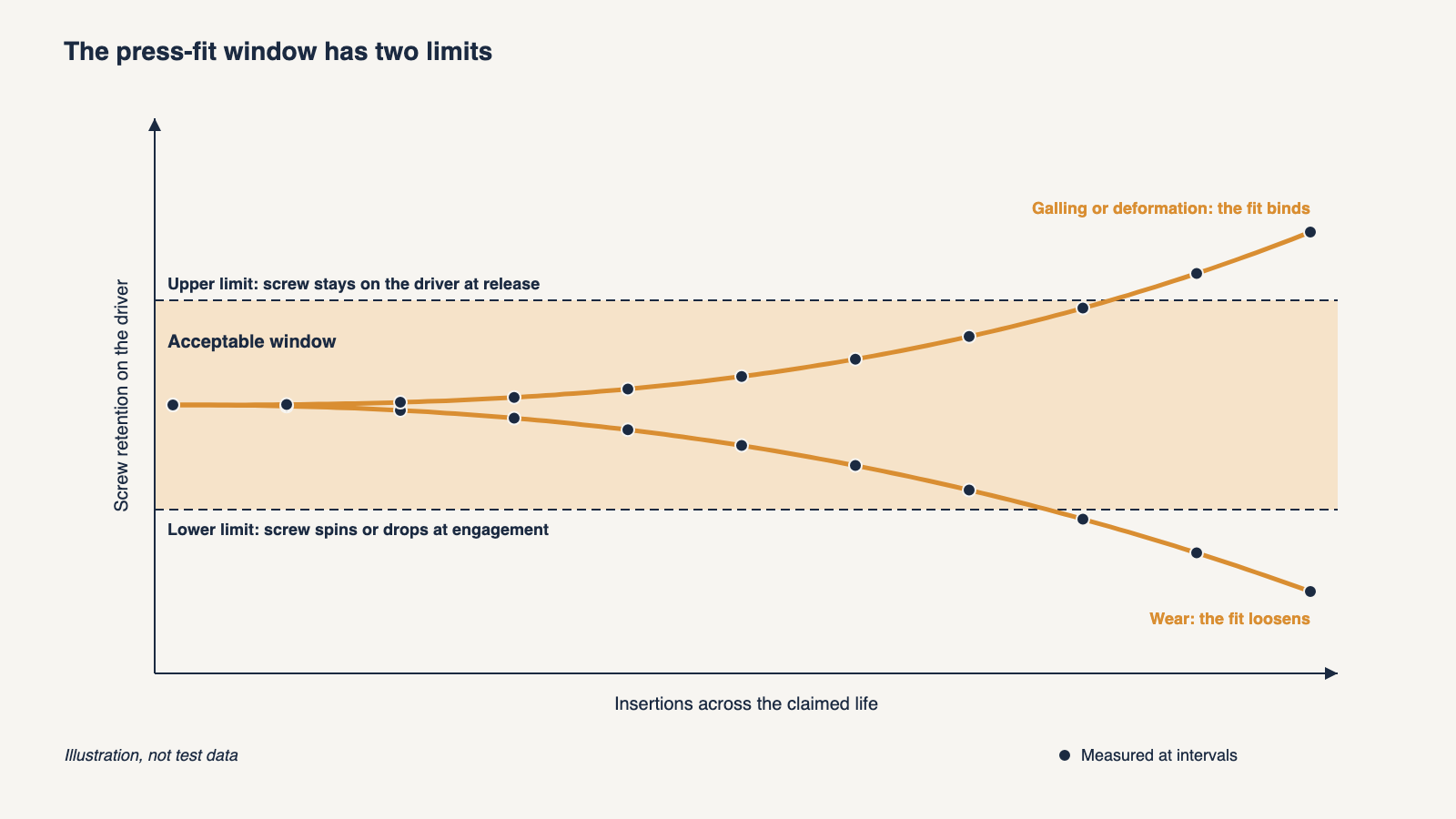
A wear protocol that only records whether something broke will miss both. The measurement set should include retention force or engagement torque at each interval, release behavior and force, and dimensional change in the engagement geometry, tracked across the full cycle count rather than compared only between the first and last unit. Degradation in these interfaces is frequently not linear, and a mid-life inflection is exactly the finding that changes a reprocessing claim.
Design margin belongs where the failure rate is
The same 2021 series separated trauma from elective procedures and found breakage rates of 0.64 percent against 0.08 percent, a 7.44 fold difference at p equal to 0.001.
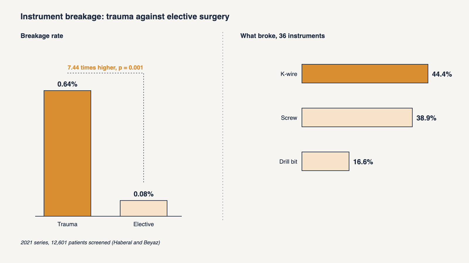
Trauma multiplies instrument failure by roughly seven, and the reasons are ordinary rather than exotic: harder bone, less favorable approach angles, faster and less controlled torque application, wet fields, and instruments further into their reprocessing life because turnover is compressed.
Validation that only exercises the nominal case therefore tests the condition where failures are least likely. A useful protocol adds off-axis engagement, degraded and end-of-life driver geometry, and torque applied at a realistic rate rather than a laboratory one. The design margin is worth spending where the observed failure rate is seven times higher, and the test plan should reflect that allocation rather than distributing effort evenly.
The short version for a program director
Analyze failure at the instrument as well as at the implant, because published breakage data is led by drill bits, wires and driver tips, not only by the hardware that stays in the patient.
Derive the durability cycle count from the reprocessing claim under ISO 17664-1 rather than from a fatigue standard, and decide both numbers in the same meeting.
Treat robotic validation as metrology, specify torque, approach vector, insertion rate, and axial load per cycle, and record them in the design history file.
Measure engagement and release separately across the full cycle range, because press-fit wear produces two different failures and only one of them looks like breakage.
Weight the test plan toward trauma conditions, where the published breakage rate runs 7.44 times higher than in elective procedures.
Common questions
Why validate the instrument as well as the implant on a cranial fixation system?
Because the instruments break too, and published data counts them. A 2020 retrospective study of 8,132 elective orthopedic cases recorded 30 instrument breakages, 0.36 percent, with drill bits the most common item and screwdriver tips two of the thirty. In a 2021 series, K-wires were 44.4 percent of breakages, screws 38.9 percent and drill bits 16.6 percent. A driver tip that rounds out during skull reconstruction is an intraoperative event.
How many insertion cycles should a durability test for a fixation driver run?
No fatigue standard gives the number. ASTM F382 estimates bone plate fatigue strength at a cycle count the tester specifies, and the FDA performance criteria for fracture fixation plates contain no fatigue test at all. The count follows from the reprocessing claim: the labeling states how long the instrument may be processed and reused, and the durability test has to cover that same lifetime, decided in the same meeting.
Why use a robot to run insertion durability tests?
To hold torque constant. Published in vitro data on pedicle screw insertion gives a mean insertion torque of 2.3 Nm, standard deviation 0.9, across 100 pedicle screws in 50 vertebrae, so torque varies a good deal from screw to screw. A torque-limiting handle controls only the ceiling. A robotic arm also holds approach angle, insertion rate and axial preload, which turns a wear test into a measurement with one isolated variable.
What should a wear test of a press-fit screw-to-blade interface measure?
Engagement and release, separately. A worn loose interface fails at engagement, where the screw spins in the driver and cannot be tightened. A galled or deformed interface fails at release, where the screw stays on the driver after placement. Record retention force or engagement torque, release behavior and release force, and dimensional change of the engagement geometry at intervals across the full cycle count, because degradation is often not linear.
Why should the test plan be weighted toward trauma conditions?
Because that is where instruments break most often. A 2021 series of 12,601 patients found instrument breakage in 0.64 percent of trauma procedures against 0.08 percent of elective ones, 7.44 times higher at p equal to 0.001. A useful protocol adds off-axis engagement, end-of-life driver geometry and torque applied at a realistic rate, instead of exercising only the nominal laboratory case where failures are least likely.
Which standards cover the testing of a reusable fixation driver?
None sets the cycle count directly. ISO 7151:2024 gives general requirements and test methods for non-cutting, articulated surgical instruments. ISO 17664-1 covers the information a manufacturer provides for processing a reusable device, including where processing has to stop, and ISO 10993-1 covers biological evaluation over the device life. ASTM subcommittees E08.05 and F04.15 handle fatigue crack formation and material test methods. The program therefore has to derive the number from its own claims.
Sources: orthopedic instrument breakage study, 2020 · orthopedic instrument breakage study, 2002 · Haberal and Beyaz, instrument breakage in trauma versus elective surgery, 2021 · open access version of the same article · cardiac surgery equipment failure study, 2022 · laparoscopic device interruption study, 2019 · operating room safety systematic review, 2013 · pedicle screw insertion torque, in vitro, 2025 · ISO 7151:2024 · ISO 17664-1:2021 · ISO 10993-1:2025 · ASTM E08.05 · ASTM F04.15
Lisa Voronkova is a medical device development expert and CEO of OVA Solutions, an R&D firm of 62 engineers that has shipped over 200 devices. She holds a PhD in applied mathematics and wrote Hardware Bible: Build a Medical Device from Scratch.
If you are building something in this space, we are glad to look at it with you. Grab a slot on Lisa’s calendar at lisavoronkova.com/booking, and if nothing there works, write to lisa@ovasolutions.com.
More on this topic: Prototyping & Product Development